Transformers | Types of Transformer | Working Principle of Transformer | Step Down Transformer | Step Up Transformer | Auto Transformer Working Principle | Current Transformer | Current Transformer Working Principle | Potential Transformer Working Principle | Auto Transforme
Transformers are electrical devices that are used to transfer electrical energy from one circuit to another through electromagnetic induction. They play a crucial role in the power distribution system, and are used in various industries. In this article, we will discuss the types of transformers, their working principle, and their applications.
What is a Transformer?
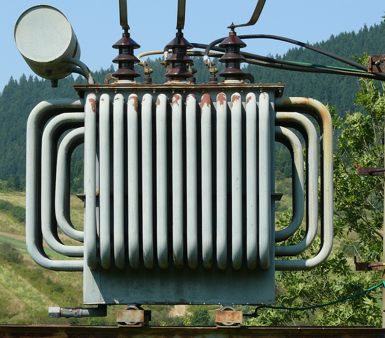
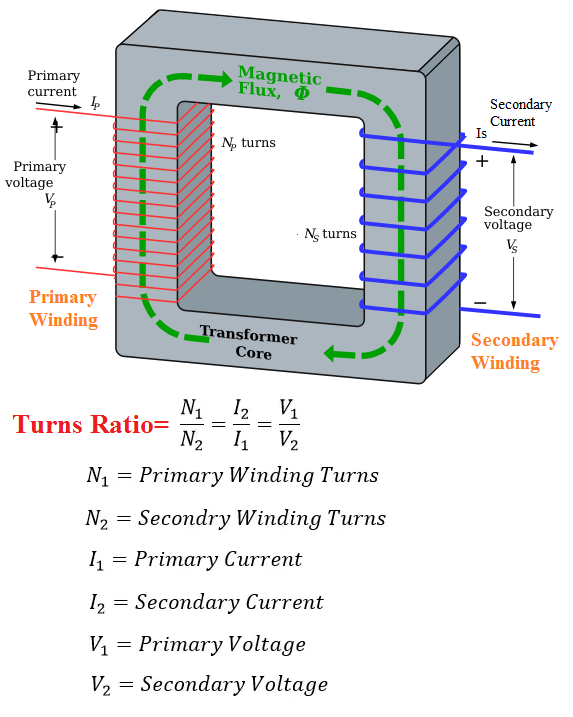
A transformer is an electrical device that is used to transfer electrical energy from one circuit to another circuit by means of electromagnetic induction. It has two or more coils that are wound on a magnetic core. The two coils are not electrically connected but are magnetically coupled to each other. The coil that is connected to the source of electrical energy is called the primary winding, while the coil that is connected to the load is called the secondary winding.
Working Principle of Transformers
The working principle of transformers is based on Faraday's law of electromagnetic induction. According to this law, when a conductor is moved in a magnetic field, an emf is induced in the conductor. In a transformer, the primary winding is connected to an AC source, which produces an alternating magnetic field. This alternating magnetic field induces an emf in the secondary winding, which results in an alternating current flowing through the secondary winding. The amount of voltage induced in the secondary winding depends on the ratio of the number of turns in the primary and secondary windings.
The transformer construction consists of a magnetic core, which is made of high permeability material such as laminated steel. The magnetic core provides a low reluctance path for the magnetic flux to flow. The transformer windings are made of copper wire and are insulated from each other and the core.
The transformer core can be either a closed core or an open core. Closed-core transformers have a magnetic core that forms a complete magnetic circuit. Open-core transformers have a magnetic core that is not completely closed, and the winding is wound around the core.
The transformer windings can be either a single winding or multiple windings. Multiple windings can be connected in series, parallel, or in a combination of series and parallel. The number of turns in the primary and secondary windings determines the voltage ratio of the transformer.
Types of Transformers
There are several types of transformers, which are classified based on their design and usage. Some of the most commonly used types of transformers are:
Step-Up Transformer
A step-up transformer is used to increase the voltage level in the secondary winding compared to the primary winding. It has more turns in the secondary winding than in the primary winding. Step-up transformers are used in power generation and transmission systems.
An example of a step-up transformer is a power transformer used in power transmission systems. These transformers are used to increase the voltage of electrical power to reduce energy loss during transmission.
For example, in a power transmission system, electrical power is generated at a relatively low voltage, typically between 11 kV and 33 kV. This low voltage power is then stepped up using a step-up transformer to a high voltage level, typically between 132 kV and 765 kV, for long-distance transmission over high-voltage power lines.
At the receiving end, another transformer called a step-down transformer is used to step down the voltage to a lower level for distribution to consumers.
The step-up transformer consists of two coils of wire wound on a common magnetic core. The coil with more turns, called the secondary winding, is connected to the high-voltage power line. The other coil with fewer turns, called the primary winding, is connected to the low-voltage power source.
When an AC voltage is applied to the primary winding, it creates an alternating magnetic field that induces an AC voltage in the secondary winding. The ratio of the number of turns in the secondary winding to the number of turns in the primary winding determines the step-up ratio of the transformer.
For example, if a transformer has a step-up ratio of 10:1, a 1000 V AC voltage applied to the primary winding will result in a 10,000 V AC voltage in the secondary winding.
Step-Down Transformer
A step-down transformer is used to decrease the voltage level in the secondary winding compared to the primary winding. It has fewer turns in the secondary winding than in the primary winding. Step-down transformers are used in power distribution systems, electronic devices, and appliances.
A step-down transformer is a type of transformer that converts a high voltage, low current AC power supply to a low voltage, high current AC power supply.
An example of a step-down transformer is a power adapter for an electronic device such as a laptop or cell phone. The adapter plugs into a wall outlet and steps down the voltage from the AC mains power supply (usually 120V or 240V) to a lower voltage suitable for the device (often 12V or 5V). The transformer inside the adapter consists of a primary winding connected to the AC mains and a secondary winding connected to the device. The turns ratio of the transformer determines the voltage reduction, and the current in the secondary winding is higher than that in the primary winding.
Another example of a step-down transformer is the distribution transformer used in power grids. These transformers are typically located on utility poles or in substations and step down the high voltage electricity transmitted over long distances (often several thousand volts) to a lower voltage suitable for use by homes and businesses.
Autotransformer
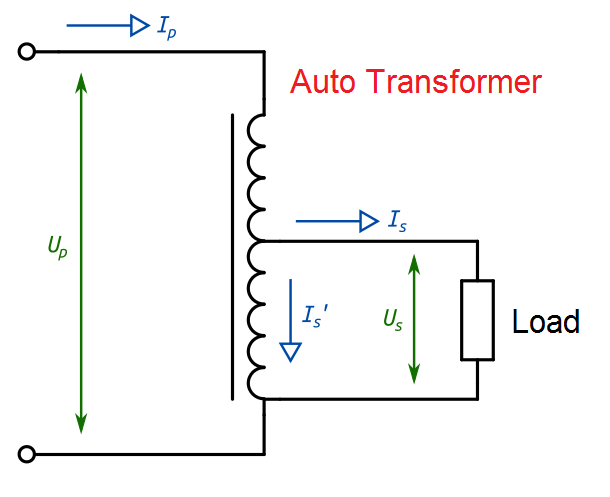
An autotransformer is a type of transformer that uses a single winding to perform the functions of both primary and secondary windings. The primary winding is connected to the source voltage, and the secondary winding is connected to the load. The winding is tapped at some point along its length, creating two separate circuits. One circuit consists of the portion of the winding between the input and output connections, while the other circuit consists of the remainder of the winding.
Autotransformer Working Principle
The autotransformer working principle is based on the concept of mutual inductance. When a voltage is applied to the primary winding, it creates a magnetic field around the winding. This magnetic field induces a voltage in the secondary winding, which is proportional to the number of turns in the winding.
In an autotransformer, the entire winding is used to transfer energy from the primary to the secondary circuit. The voltage across the entire winding is the sum of the voltage drops across each section of the winding. The voltage step-up or step-down ratio is determined by the ratio of the number of turns in the portion of the winding between the input and output connections to the total number of turns in the winding.
Autotransformer Applications
Autotransformers are used in a wide variety of applications due to their ability to step-up or step-down voltage while minimizing energy losses. Some of the common applications of autotransformers are:
Voltage Regulation
Autotransformers are commonly used to regulate the voltage in electrical power systems. By adjusting the tap on the winding, the output voltage can be increased or decreased as required.
Motor Starting
Autotransformers are used to start large induction motors that require a high starting current. By applying a reduced voltage to the motor during the starting process, the starting current is reduced, and the motor is less likely to be damaged.
Audio Systems
Autotransformers are used in audio systems to match the impedance of the speakers to the output impedance of the amplifier. This helps to ensure maximum power transfer between the amplifier and the speakers.
Current Transformer
A current transformer is used to measure the current in a circuit. It has a primary winding that is connected in series with the circuit, and a secondary winding that is connected to a measuring device. Current transformers are used in power transmission and distribution systems.
Current Transformer Working Principle
A current transformer (CT) is a device used to measure high electrical currents in power transmission systems. It works on the principle of electromagnetic induction, where a current in a primary circuit (the high current circuit) induces a proportional current in a secondary circuit (the low current circuit).
The CT consists of a primary winding and a secondary winding wound on a common magnetic core. The primary winding is connected in series with the high current circuit, while the secondary winding is connected to a measuring instrument or a protective relay.
When a high current flows through the primary winding, it produces a magnetic field that induces a voltage in the secondary winding. The magnitude of the induced voltage is proportional to the current flowing through the primary winding. By knowing the turns ratio of the transformer, the primary current can be calculated from the secondary current.
The CT provides electrical isolation between the high voltage circuit and the measuring or protective equipment connected to the secondary winding. This allows for safe and accurate measurement of high electrical currents without the need for direct connection to the circuit.
CTs are widely used in power transmission and distribution systems to provide accurate current measurement for metering, protection, and control purposes.
Potential Transformer
A potential transformer is used to measure the voltage in a circuit. It has a primary winding that is connected in parallel with the circuit, and a secondary winding that is connected to a measuring device. Potential transformers are used in power transmission and distribution systems.
Potential Transformer Working Principle
A potential transformer is a type of instrument transformer that is used to step down high voltage levels to lower, more manageable levels for use in instruments and meters. Its working principle is based on the principle of electromagnetic induction.
The potential transformer consists of a primary winding, which is connected to the high voltage source, and a secondary winding, which is connected to the instrument or meter. The number of turns in the primary winding is greater than the number of turns in the secondary winding, which results in a step-down ratio.
When the high voltage current flows through the primary winding, it generates a magnetic field around the winding. This magnetic field induces a voltage in the secondary winding according to Faraday's Law of Electromagnetic Induction. The induced voltage in the secondary winding is proportional to the voltage in the primary winding, and is typically much lower than the primary voltage.
The potential transformer is designed to have a high impedance on the secondary side, which means that it draws very little current from the instrument or meter that it is connected to. This ensures that the instrument or meter is not loaded down by the transformer and that the voltage measurement is accurate.
Applications of Transformers
Transformers are used in various applications, such as:
Power Generation
Transformers are used in power generation systems to step up the voltage level for transmission over long distances. This reduces the energy losses in the transmission lines and makes the power distribution more efficient.
Power Transmission and Distribution
Transformers are used in power transmission and distribution systems to step up and step down the voltage level, depending on the distance of the transmission line and the power demand.
Electronic Devices
Transformers are used in electronic devices, such as audio amplifiers and power supplies, to step up or step down the voltage level.
Industrial Applications
Transformers are used in various industrial applications, such as welding machines, electric motors, and arc furnaces.
Summary
Transformers are essential devices in the power distribution system and are used in various industries. They work on the principle of mutual induction and can be classified based on their design and usage. Understanding the types and working principle of transformers is crucial in the design and operation of electrical systems.
FAQs
What is the difference between a step-up transformer and a step-down transformer?
A step-up transformer is used to increase the voltage level in the secondary winding, while a step-down transformer is used to decrease the voltage level in the secondary winding.
What is an autotransformer?
An autotransformer has a single winding that acts as both the primary and secondary winding. It is used to step up or step down the voltage level in a circuit.
What is a current transformer?
A current transformer is used to measure the current in a circuit. It has a primary winding that is connected in series with the circuit, and a secondary winding that is connected to a measuring device.
What is a potential transformer?
A potential transformer is used to measure the voltage in a circuit. It has a primary winding that is connected in parallel with the circuit, and a secondary winding that is connected to a measuring device.
What is the importance of transformers in power distribution systems?
Transformers are used in power distribution systems to step up and step down the voltage level, depending on the distance of the transmission line and the power demand. This makes the power distribution more efficient and reduces energy losses.


Post a Comment