Capacitors in Series | Capacitors in Series Calculator | Capacitors in Series And Parallel | Capacitors in Series And Parallel Examples | Capacitors in Parallel | Capacitors in Parallel Calculator
Capacitors are passive electronic components that store electrical charge and are widely used in electronic circuits for a variety of purposes such as filtering, smoothing, and regulating voltage. In this article, we will explore the differences between series and parallel capacitors, Capacitors in Series, Capacitors in Parallel and their applications in electronic circuits.
Series Capacitors:
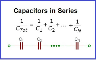
In a series circuit, capacitors are connected end-to-end to form a chain, with the total capacitance being less than any individual capacitor. This is because the charge is shared between the capacitors, and the effective capacitance is reduced. The voltage across each capacitor in a series circuit is proportional to its capacitance value, and the total voltage across the series capacitors is equal to the sum of the individual voltage drops.
Example of Capacitors in Series Calculation
One of the main applications of series capacitors is to block DC signals while allowing AC signals to pass through. This is achieved by connecting a series capacitor in-line with the signal path, which creates a high-pass filter that attenuates low-frequency signals. Series capacitors are also used to reduce the effective capacitance of a circuit, which is useful in applications such as voltage dividers where the voltage is divided between the capacitors.
Another important application of series capacitors is in AC voltage dividers, where a high-voltage AC signal is divided into lower voltages using a series of capacitors and resistors. In this case, the capacitors are used to block DC signals and allow only the AC component to pass through.
Example 1: Voltage Divider Circuit
One common application of capacitors in series is in a voltage divider circuit. In this circuit, two capacitors with different capacitances are connected in series, along with a resistor. The voltage across the second capacitor is used as the output voltage, which is a fraction of the input voltage. The ratio of the two capacitor values determines the output voltage, and this can be adjusted by varying the values of the capacitors.
Example 2: High-Voltage Capacitor Banks
Another application of capacitors in series is in high-voltage capacitor banks. These are used in various industrial and scientific applications, such as in particle accelerators and pulsed power systems. By connecting many capacitors in series, a large overall capacitance can be achieved while maintaining a high voltage rating. This allows for the storage and release of large amounts of electrical energy in a short period of time.
Example 3: AC Filter Circuits
Capacitors in series can also be used in AC filter circuits, which are used to filter out unwanted frequencies from AC power sources. In these circuits, multiple capacitors with different capacitances are connected in series and parallel, along with resistors and inductors. This creates a complex network that can filter out specific frequencies, depending on the values of the components. AC filter circuits are commonly used in power supplies, audio amplifiers, and other electronic devices.
Example 4: Voltage Multiplier Circuits
In voltage multiplier circuits, multiple capacitors in series are used to create a high-voltage output from a low-voltage input. This is achieved by charging the capacitors in series and then discharging them in parallel, which results in a higher overall voltage. Voltage multiplier circuits are commonly used in CRT displays, voltage multipliers, and other high-voltage applications.
Example 5: Tuned Circuits
Capacitors in series can also be used in tuned circuits, which are used to select a specific frequency from a range of frequencies. Tuned circuits consist of multiple capacitors and inductors connected in series and parallel, forming a resonant circuit. The values of the components are chosen so that the circuit resonates at the desired frequency, and this can be used to select or filter out that frequency.
Parallel Capacitors:
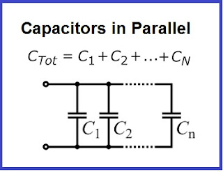
In a parallel circuit, capacitors are connected side-by-side, with each capacitor connected to the same voltage source. The total capacitance of a parallel circuit is equal to the sum of the individual capacitance values, and the voltage across each capacitor is equal to the source voltage. When capacitors are connected in parallel, the charge is shared between them, and the effective capacitance is increased.
Example of Capacitors in Parallel Calculation
Parallel capacitors are commonly used to filter out high-frequency noise from a circuit or to smooth out voltage fluctuations. This is achieved by connecting a parallel capacitor across the power supply or signal line, which acts as a low-pass filter that attenuates high-frequency signals. Parallel capacitors are also used to increase the effective capacitance of a circuit, which is useful in applications such as power supply filters where the capacitors are used to store energy and reduce the ripple voltage.
In some cases, parallel capacitors are also used to balance the voltage distribution in a circuit. For example, if there is a voltage drop across a particular section of the circuit, a parallel capacitor can be connected to that section to balance the voltage and prevent any unwanted noise or distortion.
Example 1: Power Supply Filtering
One common application of capacitors in parallel is in power supply filtering. In this application, capacitors are used to smooth out the output voltage of a power supply by filtering out unwanted AC signals. The capacitors are connected in parallel to the output of the power supply, and they act as a low-pass filter, allowing only the DC component of the output voltage to pass through.
Example 2: Audio Crossover Networks
Another application of capacitors in parallel is in audio crossover networks. These are used in audio systems to split the audio signal into different frequency ranges, which are then sent to different speakers or amplifiers. Capacitors are used to block or attenuate certain frequencies, allowing only the desired frequency range to pass through. Capacitors in parallel are used to create high-pass filters, which allow only high-frequency signals to pass through.
Example 3: Coupling and Decoupling
Capacitors in parallel can also be used for coupling and decoupling in electronic circuits. Coupling capacitors are used to pass AC signals from one stage of an amplifier to another, while blocking DC signals. Decoupling capacitors are used to filter out unwanted noise and ripple from power supplies. Both coupling and decoupling capacitors are commonly used in audio amplifiers, RF circuits, and other electronic devices.
Example 4: Snubber Circuits
Snubber circuits are used to protect electronic components from voltage spikes and transient signals. Capacitors in parallel are often used in snubber circuits, along with resistors and diodes. The capacitors absorb the energy from the transient signals, while the other components dissipate the energy as heat. Snubber circuits are commonly used in power supplies, motor control circuits, and other high-power applications.
Example 5: Energy Storage
Capacitors in parallel can also be used for energy storage in various applications. By connecting multiple capacitors in parallel, a large overall capacitance can be achieved, allowing for the storage and release of large amounts of electrical energy in a short period of time. This can be used in various applications, such as flash photography, pulsed lasers, and other high-power applications.
Applications:
Series and parallel capacitors are used in many different applications in electronic circuits. Series capacitors are commonly used to block DC signals or to filter AC signals. They are also used to reduce the effective capacitance of a circuit, which can be useful in applications such as voltage dividers.
Parallel capacitors are commonly used to filter out high-frequency noise from a circuit or to smooth out voltage fluctuations. They are also used to increase the effective capacitance of a circuit, which can be useful in applications such as power supply filters.
Conclusion:
In summary, series and parallel capacitors have different applications in electronic circuits. Series capacitors are used to block DC signals, reduce the effective capacitance of a circuit, and create voltage dividers. Parallel capacitors, on the other hand, are used to filter out high-frequency noise, increase the effective capacitance of a circuit, and balance the voltage distribution.
Understanding the differences between series and parallel capacitors and their applications is crucial for designing and analyzing electronic circuits. By carefully selecting and connecting the capacitors in a circuit, designers can achieve the desired performance characteristics and ensure reliable operation of the circuit.
Frequently Asked Questions (FAQ)
Q: How do you determine if a capacitor is in series or parallel?
A: Capacitors are said to be in series when they are connected end to end, such that the output of one capacitor is connected to the input of the next capacitor. Capacitors are said to be in parallel when they are connected side by side, such that the inputs of all capacitors are connected together, and the outputs of all capacitors are connected together.
Q: What are parallel capacitors?
A: Parallel capacitors are a set of capacitors connected side by side, such that the inputs of all capacitors are connected together, and the outputs of all capacitors are connected together. When capacitors are connected in parallel, the total capacitance is equal to the sum of the individual capacitances.
Q: What is capacitor series?
A: Capacitor series refers to a set of capacitors connected end to end, such that the output of one capacitor is connected to the input of the next capacitor. When capacitors are connected in series, the total capacitance is less than any individual capacitance.
Q: What is capacitor and SI unit?
A: A capacitor is an electronic component that stores electrical energy in an electric field. The SI unit of capacitance is the farad (F).
Q: What is the SI unit of capacitor in series?
A: The SI unit of capacitance is the farad (F) regardless of whether the capacitors are in series or parallel.
Q: What is capacitor formula?
A: The formula for capacitance is C = Q/V, where C is the capacitance in farads, Q is the charge stored in the capacitor in coulombs, and V is the voltage across the capacitor in volts.
Q: What is the formula of parallel capacitor?
A: The formula for calculating the total capacitance of capacitors connected in parallel is C = C1 + C2 + C3 + ..., where C1, C2, C3, etc. are the capacitances of the individual capacitors.
Q: What is the value of 1 capacitor?
A: The value of 1 capacitor depends on its capacitance, which is measured in farads (F). Capacitors can have a wide range of capacitance values, from picofarads (pF) to microfarads (μF) to farads (F) and beyond.


Post a Comment