Astable Multivibrator | Astable Multivibrator using 555 Timer | Astable Multivibrator using 555
An astable multivibrator is an electronic circuit that generates a continuous square wave without any external triggering. This circuit is commonly used in electronic devices such as timers, oscillators, and tone generators. In this article, we will dive deep into the working principle, construction, and applications of the astable multivibrator.
Astable Multivibrator | Astable Multivibrator using 555 Timer | Astable Multivibrator using 555
- Astable multivibrator is an electronic oscillator circuit that generates a square wave.
- It is a type of free-running multivibrator that does not require an external trigger to change states.
- Astable multivibrators are commonly used in applications such as timing circuits, pulse generators, and tone generators.
- The circuit consists of two transistors, two capacitors, and some resistors.
- The output waveform of the Astable multivibrator is symmetrical, with equal high and low times.
- The frequency of the output waveform can be adjusted by changing the values of the capacitors and resistors in the circuit.
- Astable multivibrators are relatively easy to construct and can be built using common electronic components.
- The circuit can be analyzed using various methods, including the transient response, steady-state response, and frequency analysis.
- Astable multivibrators can be modified to include additional components, such as diodes or transistors, to create more complex waveforms.
- Applications of Astable multivibrators include timing circuits in digital systems, pulse generation in communication systems, and tone generation in audio circuits.
What is an Astable Multivibrator?
Working Principle | Operation of Astable Multivibrator
The astable multivibrator consists of two amplifying stages connected in a positive feedback loop. The two stages are coupled through a coupling capacitor and are biased through resistors. The capacitor charges and discharges alternatively through the two stages, generating a continuous square wave.
The astable multivibrator circuit is composed of two transistors, Q1 and Q2, which are connected in a positive feedback loop. The collector of Q1 is connected to the base of Q2 through capacitor C1, and the collector of Q2 is connected to the base of Q1 through capacitor C2. Both transistors have their emitters connected to ground. The circuit also includes equal value collector load resistors R1 and R4, and equal value biasing resistors R2 and R3. The capacitors C1 and C2 are also of equal value. This configuration creates a circuit that oscillates continuously, generating a square wave output
When power is supplied to the circuit, the capacitor starts charging through one of the stages, and the transistor in that stage starts conducting. This causes the capacitor to discharge through the second stage, and the transistor in that stage also conducts. The cycle repeats, and the capacitor charges and discharges alternatively through the two stages, generating a square wave output.
Construction:
The astable multivibrator can be constructed using discrete components such as resistors, capacitors, and transistors, or integrated circuits such as the 555 timer. The circuit can be designed with various combinations of components, depending on the desired output frequency and duty cycle.
One popular configuration of the astable multivibrator uses two NPN transistors, resistors, and capacitors. The base of each transistor is connected to a resistor, which is connected to the positive supply. The collector of each transistor is connected to the negative supply through a resistor, and the two collectors are connected through a coupling capacitor. The emitter of each transistor is connected to a common resistor, which is connected to the negative supply.
Astable Multivibrator using 555 Timer | Astable Multivibrator using 555
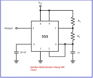
An astable multivibrator is a type of oscillator circuit that produces a continuous output waveform without any external input signal. This circuit can be easily implemented using a 555 timer IC.
Circuit diagram for an astable multivibrator using a 555 timer:
How the circuit works:
The two resistors R1 and R2, along with the capacitor C1, determine the frequency of the output waveform.
When power is applied, the capacitor C1 charges through resistor R1 and the 555 timer's internal comparator.
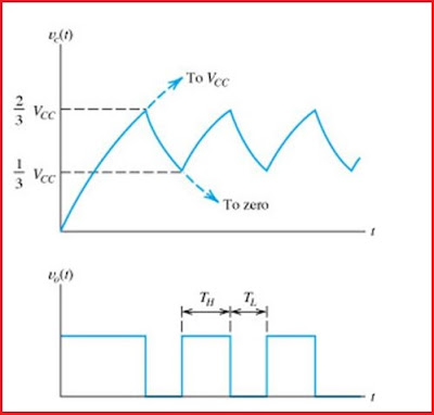
Once the voltage across C1 reaches 2/3 of the supply voltage, the output of the first comparator flips high and the discharge transistor is turned off, allowing C1 to discharge through R2.
Once the voltage across C1 drops below 1/3 of the supply voltage, the output of the second comparator flips low and the discharge transistor is turned on again, allowing C1 to start charging again.
This cycle repeats, producing a continuous oscillation between high and low states.
Adjust the frequency of the output waveform by changing the values of R1, R2, and C1. The formula for calculating the frequency of the output waveform is:
f = 1.44 / ((R1 + 2 * R2) * C1)
where f is the frequency in Hertz, R1 and R2 are in ohms, and C1 is in farads.
Astable Multivibrator Frequency Table
ASTABLE MULTIVIBRATOR WAVEFORM
The astable multivibrator circuit generates a square wave output. The waveform of the astable multivibrator circuit consists of a series of high and low pulses, where the duration of each pulse is equal to the time constant of the circuit. The time constant is determined by the values of the resistors and capacitors used in the circuit. The rise and fall times of the pulses are typically very short, making the output waveform of the astable multivibrator circuit well-suited for applications that require a high-frequency square wave. The frequency of the output waveform is determined by the values of the resistors and capacitors used in the circuit, as discussed in the article.
Applications:
The astable multivibrator has numerous applications in electronic circuits. Some of the common applications are:
Timers: The astable multivibrator can be used as a timer to generate a square wave output, which can be used to trigger other circuits.
Oscillators: The astable multivibrator can be used as an oscillator to generate a continuous square wave output at a fixed frequency.
Tone Generators: The astable multivibrator can be used as a tone generator to generate audio signals of different frequencies.
LED Blinkers: The astable multivibrator can be used as an LED blinker to generate a square wave output, which can be used to blink LEDs.
Factors Affecting the Astable Multivibrator Frequency
Conclusion
In conclusion, the astable multivibrator is a versatile electronic circuit that can be used in a variety of applications. Its simple construction, low cost, and low power consumption make it a popular choice in electronic circuits. By understanding the working principle and construction of the astable multivibrator, engineers can design circuits that meet specific requirements and perform various functions.
FAQ
Q: What is meant by astable multivibrator?
A: Astable multivibrator is an electronic oscillator circuit that generates a continuous square wave output without the need for an external trigger or input signal. It is called "astable" because it has no stable state, and it continuously switches back and forth between two unstable states.
Q: What is the use of astable multivibrator?
A: Astable multivibrators are commonly used in electronic circuits for generating square wave pulses, timing circuits, and clock generators. They are also used in applications such as tone generators, flashing lights, and electronic alarms.
Q: What is the working principle of an astable multivibrator?
A: An astable multivibrator consists of two amplifying stages, each with a capacitor and a resistor. The circuit is designed such that the two stages are cross-coupled, and the output of one stage triggers the other. As a result, the circuit oscillates, producing a continuous square wave output.
Q: What is the state of astable multivibrator?
A: Astable multivibrator does not have a stable state. It continuously switches back and forth between two unstable states, which results in the production of a continuous square wave output.
Q: What are the applications of multivibrator?
A: Multivibrators find various applications in electronics, such as in timing circuits, pulse generators, frequency dividers, frequency modulators, frequency synthesizers, digital systems, and many other applications where a stable or precise frequency waveform is required.
Q: What is meant by 555 astable multivibrator?
A: The 555 timer IC is a versatile and widely used integrated circuit that can be configured as an astable multivibrator. The 555 astable multivibrator generates a continuous square wave output without the need for an external trigger or input signal.
Q: Why is it called astable?
A: The term "astable" refers to the fact that the circuit does not have a stable state. It continuously switches back and forth between two unstable states, resulting in the production of a continuous square wave output.
Q: Why is it called a multivibrator?
A: The name "multivibrator" is derived from the fact that the circuit has multiple stable states. Depending on the type of multivibrator, the circuit can switch back and forth between two or more stable states.
Q: What is called a multivibrator?
A: A multivibrator is an electronic circuit that has two or more stable states and can switch back and forth between these states to produce a periodic waveform. The name "multivibrator" is derived from the fact that the circuit can vibrate between multiple stable states.


Post a Comment